Are the car wheels parallel when steering?
It happens that geometry and mechanics are precisely what you need to define how the wheels of your car must be turned.
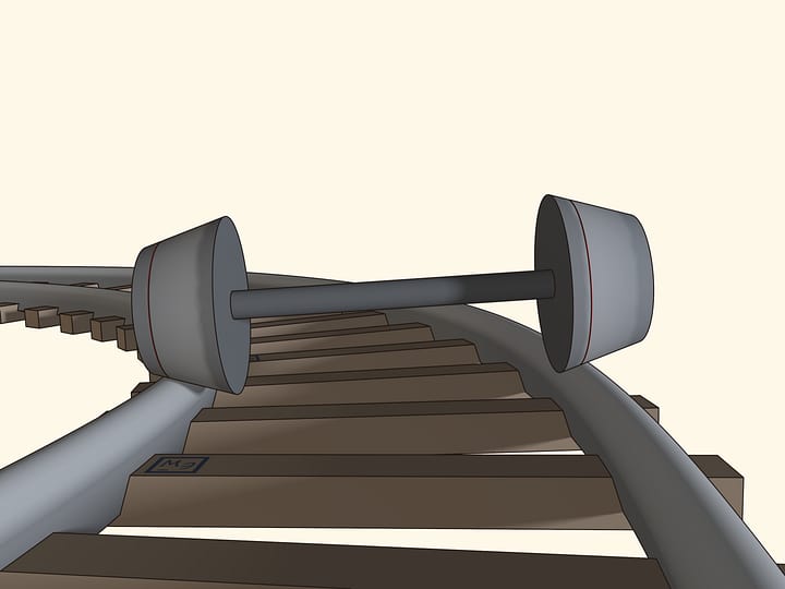
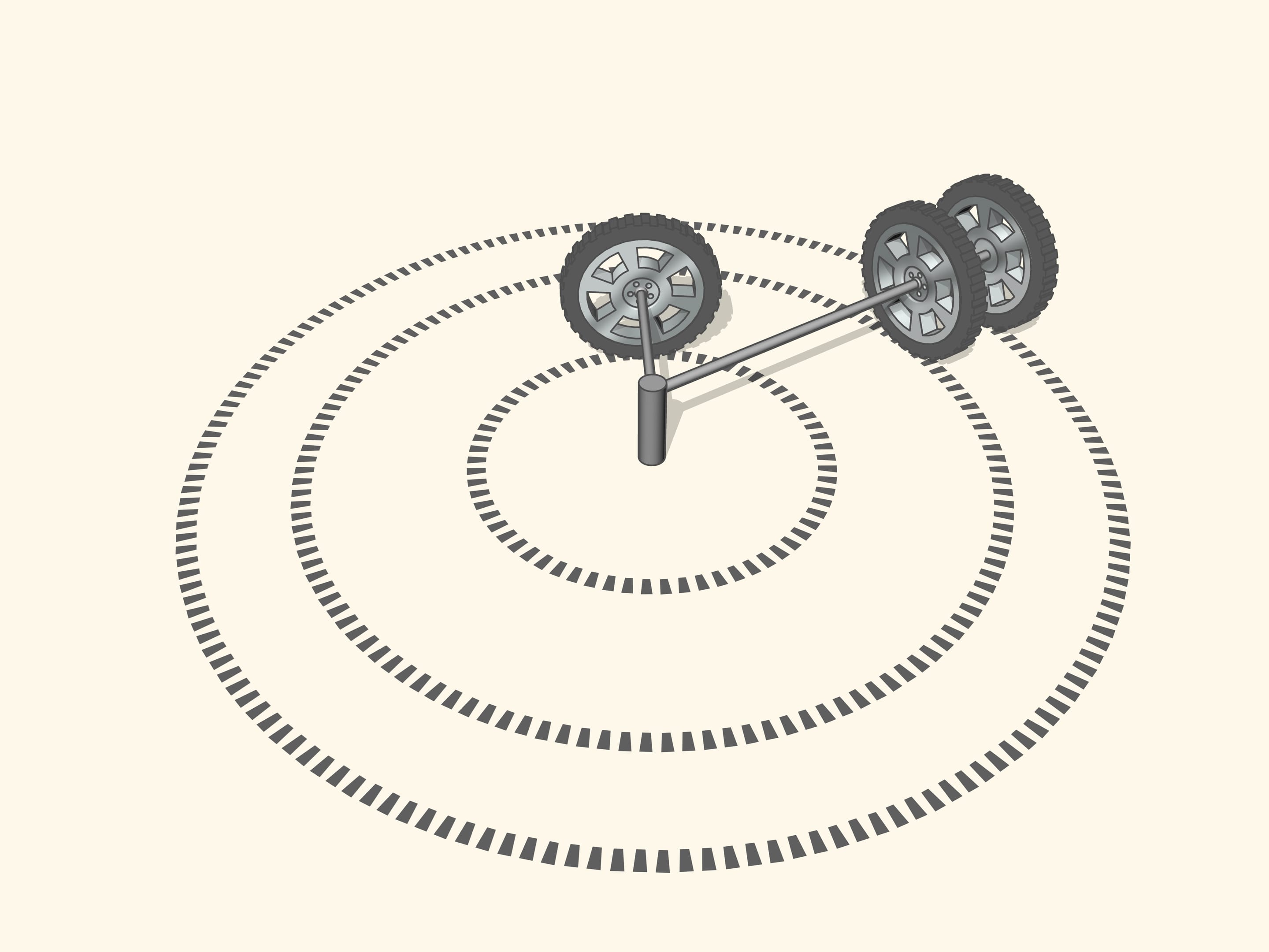
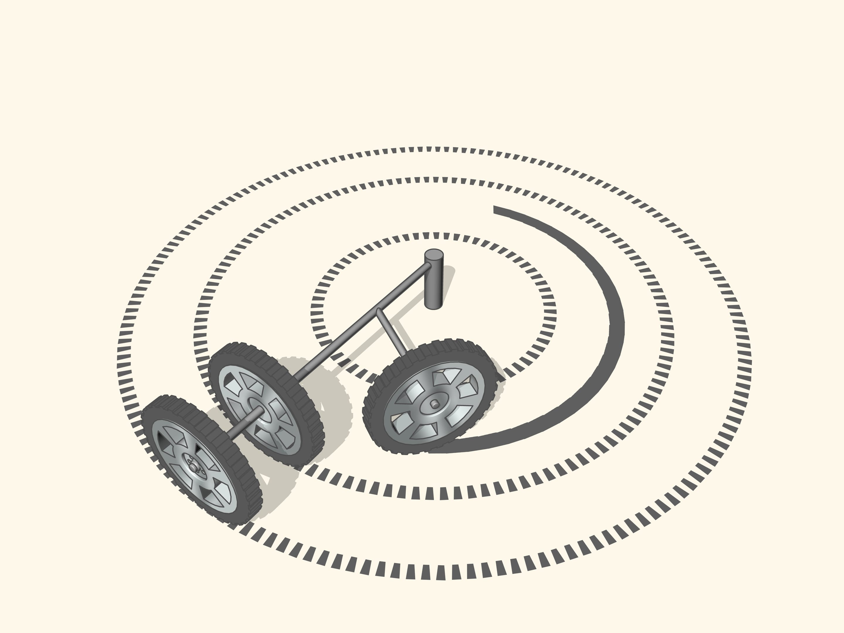
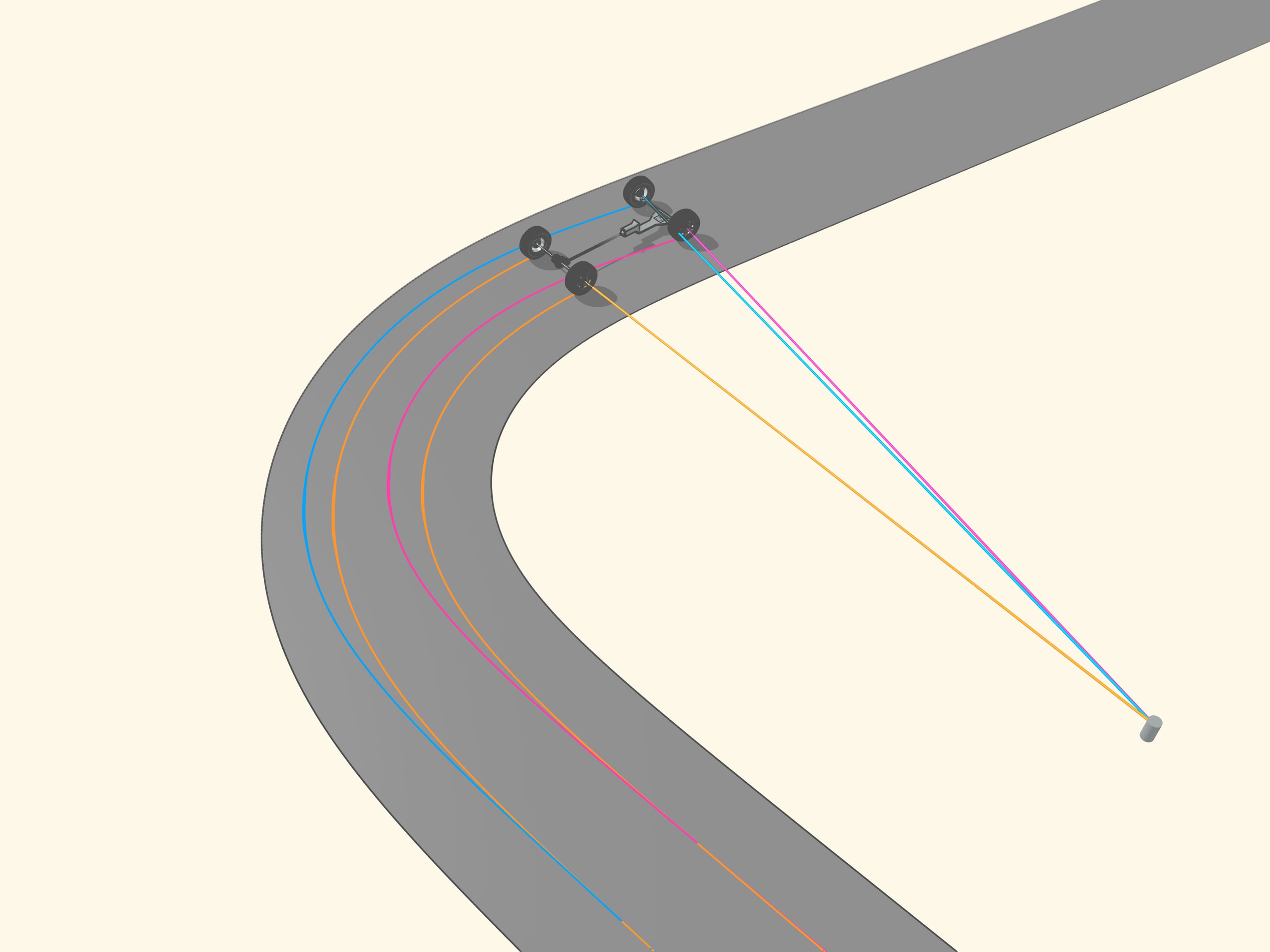
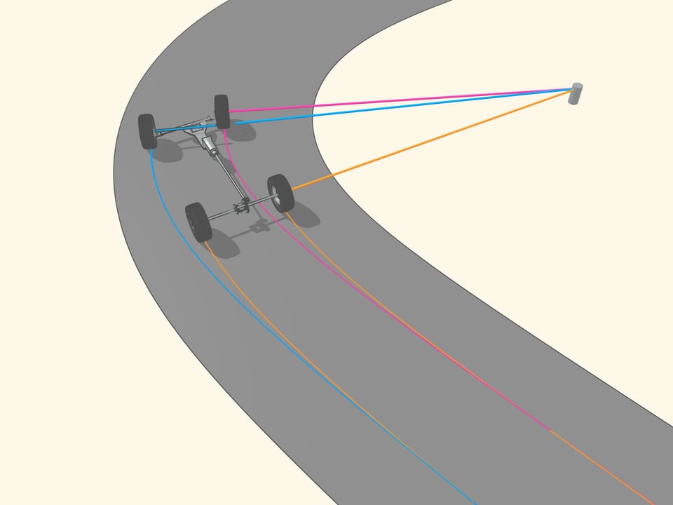
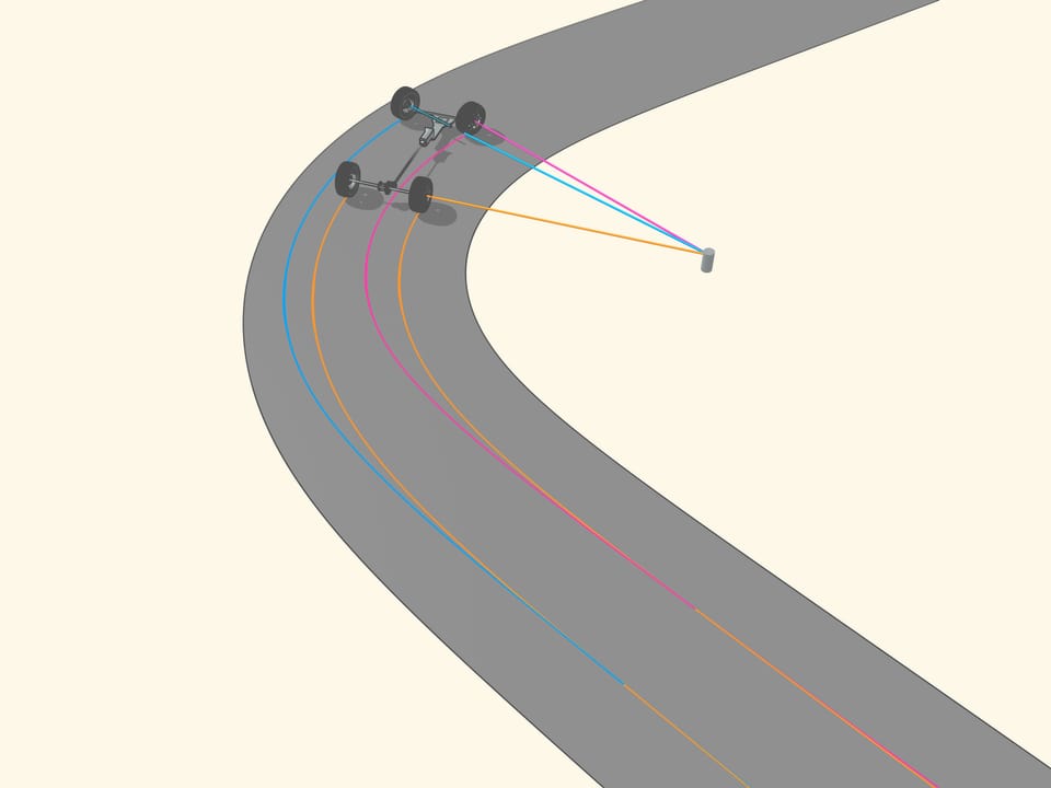
If the prolongation of the wheel axis passes through the centre of rotation, then the wheel, while turning, leave a clear tread. If the prolongation of the wheel axis is not directed toward the centre of rotation, then the wheel skids as it turns. The tread will be erased from the skidding, and, above all, the control of a vehicle with wheels like that will be increasingly difficult as the speed increases. So, for a good control of the car the prolongations of the axes of all the wheels must be directed toward the centre of rotation. But what this means for a car with four wheels?


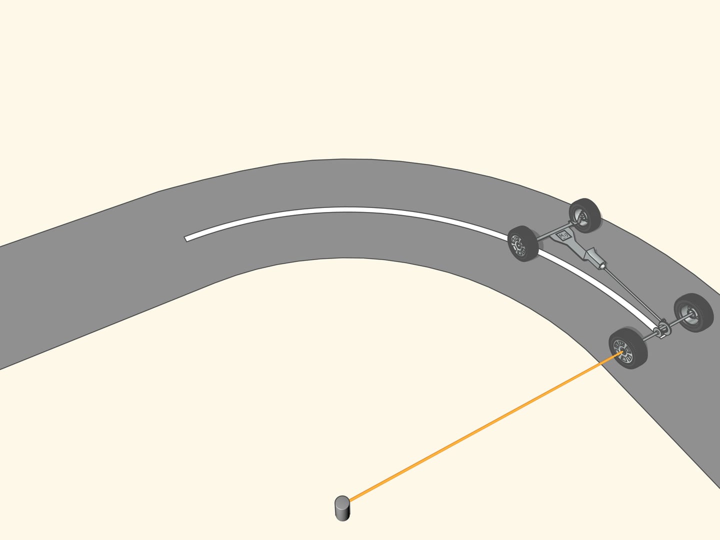
To begin, let us learn to move along a simple curve, i.e., an arc of a circle.
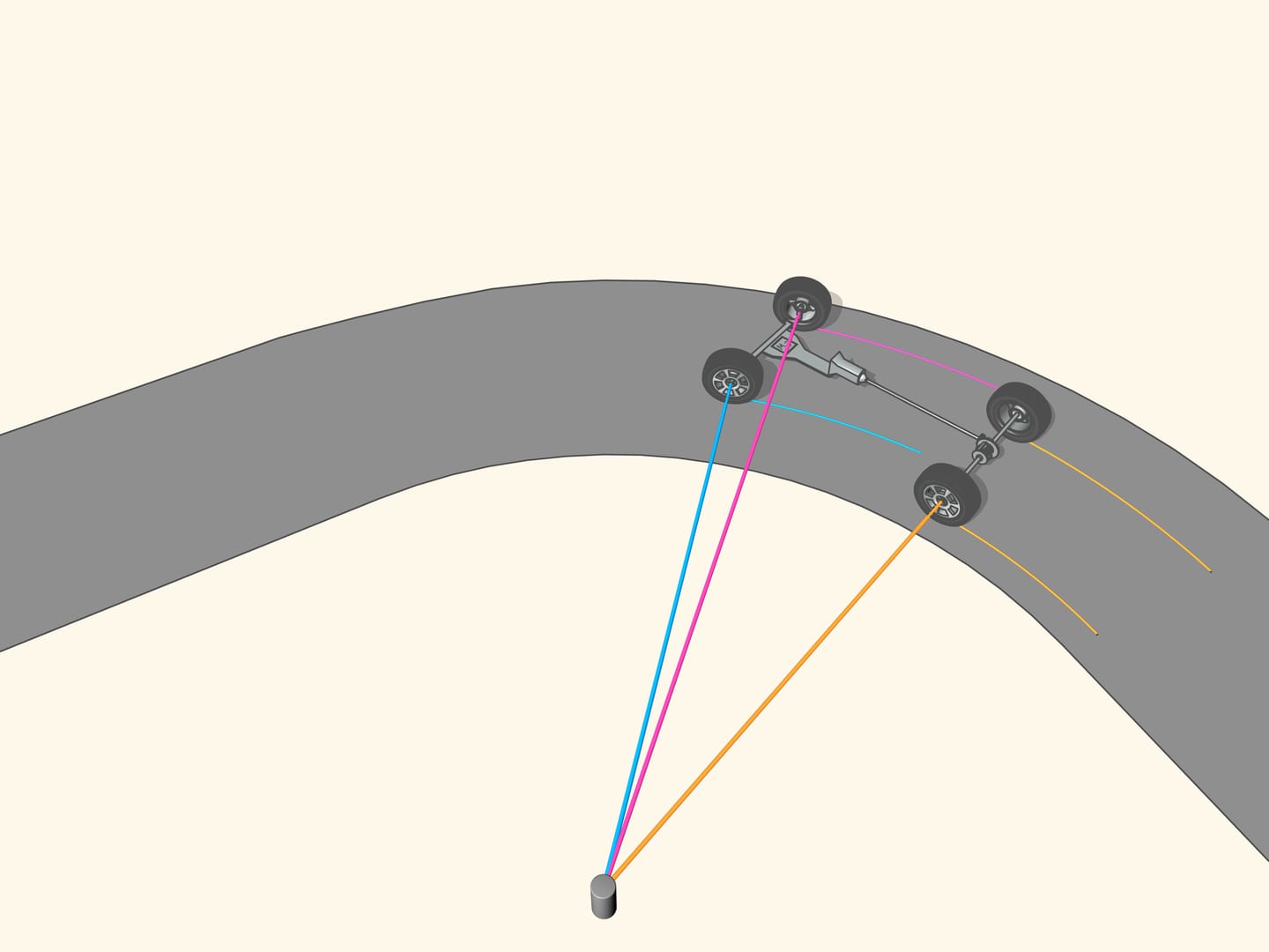
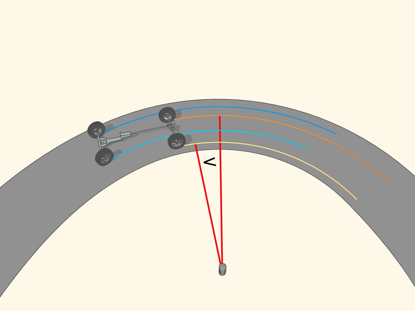
Since the axle of rear wheel in most cars is fixed, the prolongation of this axle should be directed toward the centre of this circle. The front wheels are then turned so that the axis of each is directed toward the same centre. This means that for a good control one should be able to turn the front wheels by different angles, so that these wheels will be non parallel!
You will say that the curves are not always arcs of circles, and in addition that the car does not stop, before steering. This, of course, is true, but it happens that along any curve we can consider that at every time the car moves along an arc of a circle whose radius and centre depend on that moment of time.
Consider an ordinary road. In order to be viable by car, it must have no sharp angles, namely, its middle line must be, as mathematicians say, a smooth curve.
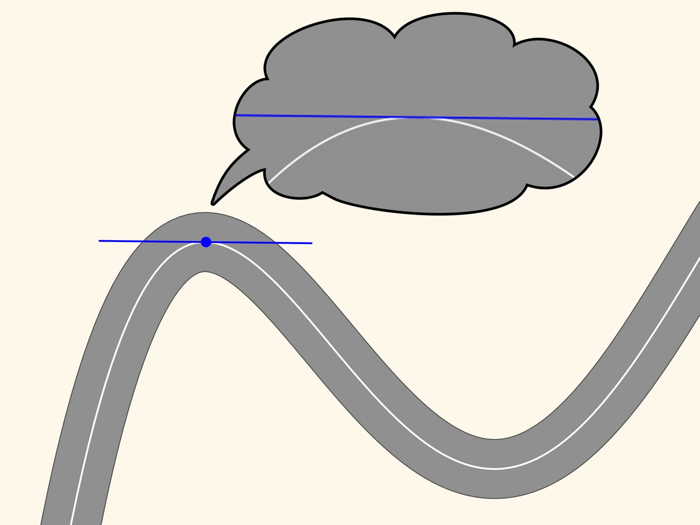
Take any point on this line and mark it in red, and another, a little far from the first, marked in blue. These two points define a unique straight line connecting them, and we draw that line. Now move the red point along the curve toward the blue point. At a time when the points coincide, the line defined by them will become the tangent line. It is the linear approximation of the curve in a small neighbourhood of that point. We observe, however, zooming in, that the curve and the straight line are close only for a small stretch.
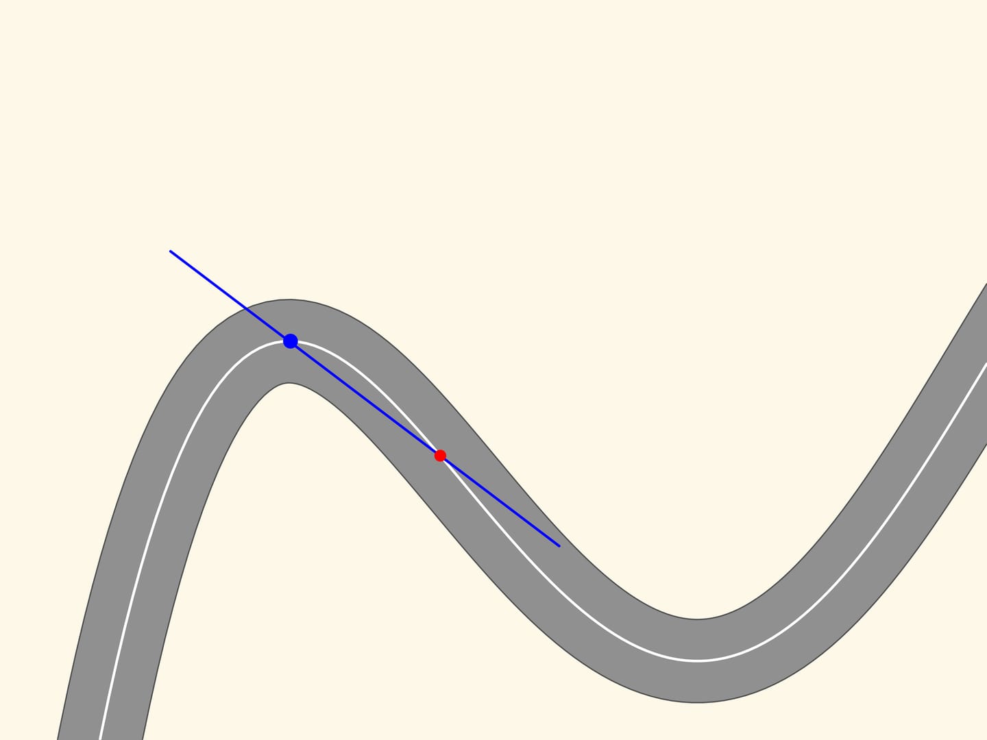
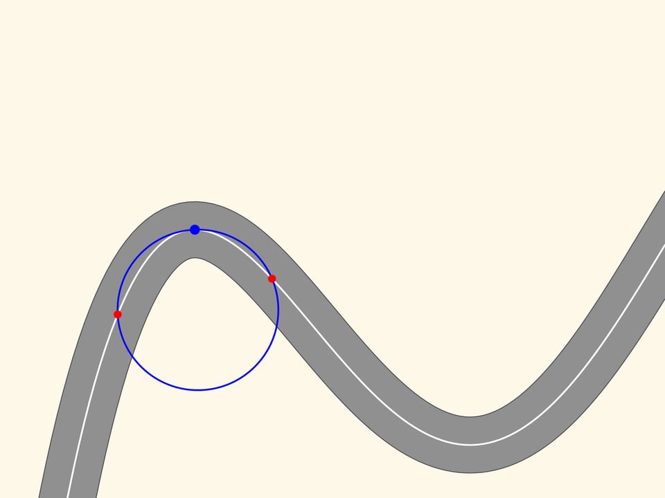
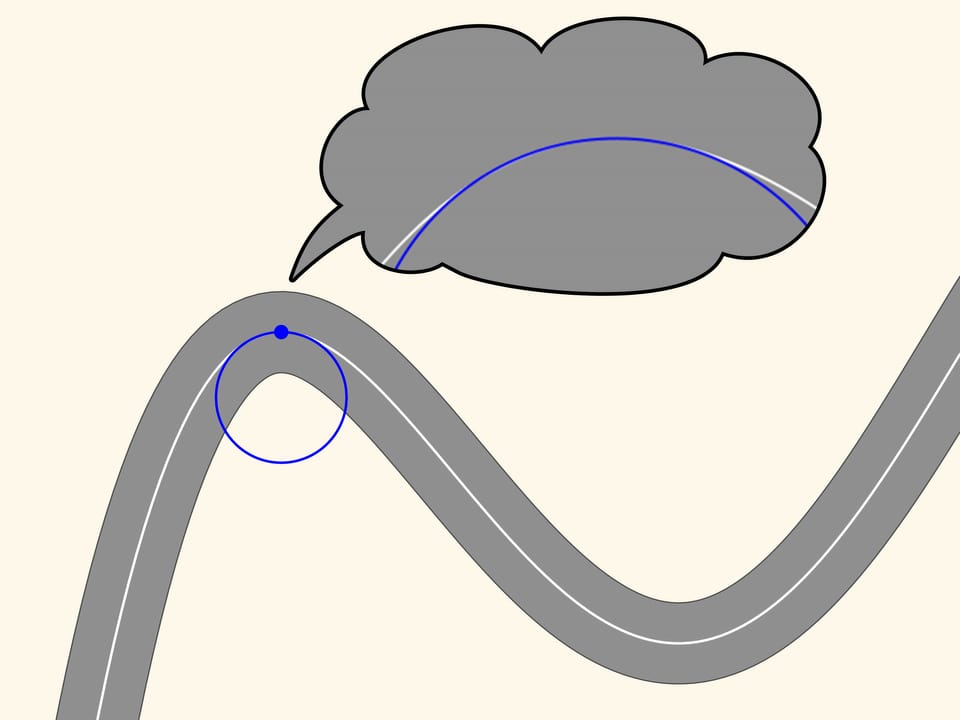
Let us now take two red points on the curve, one on the right and one on the left of the blue point. Three points, which do not lie on a straight line, define a unique circle, that we draw. Now we move the two red points towards the blue point. When the three points coincide we get a circle, which is called osculating. It is the second order approximation of the curve, and zooming in we may see that this approximation is better. We observe that in a stretch of the curve, along which the radius of curvature increases or decreases (as in the ascending and descending parts of the curve in the figure) the osculating circle always intersects the curve, differently from the tangent, which is situated in the same part of the plane cut off by the curve, in a neighbourhood of the point of tangency.
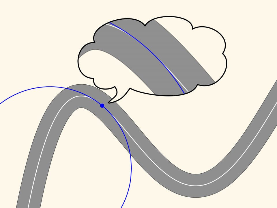
Since the osculating circle in our case well approximates the curve and can be constructed at each point, the motion along a road with curves can be considered at every instant of time as the motion along an arc of a circle. The radius and the centre of this circle depend, obviously, from where the car is.
In this way, while moving along a certain curve, one can imagine that at every time the car moves on a small arc of a circle. And our first case, where the road is exactly an arc of a circle, is therefore essential to study the motion.

But how to get that for any position of the steering wheels the prolongation of the axes are directed toward the instantaneous centre of curvature (i.e., the centre of the corresponding osculating circle)?
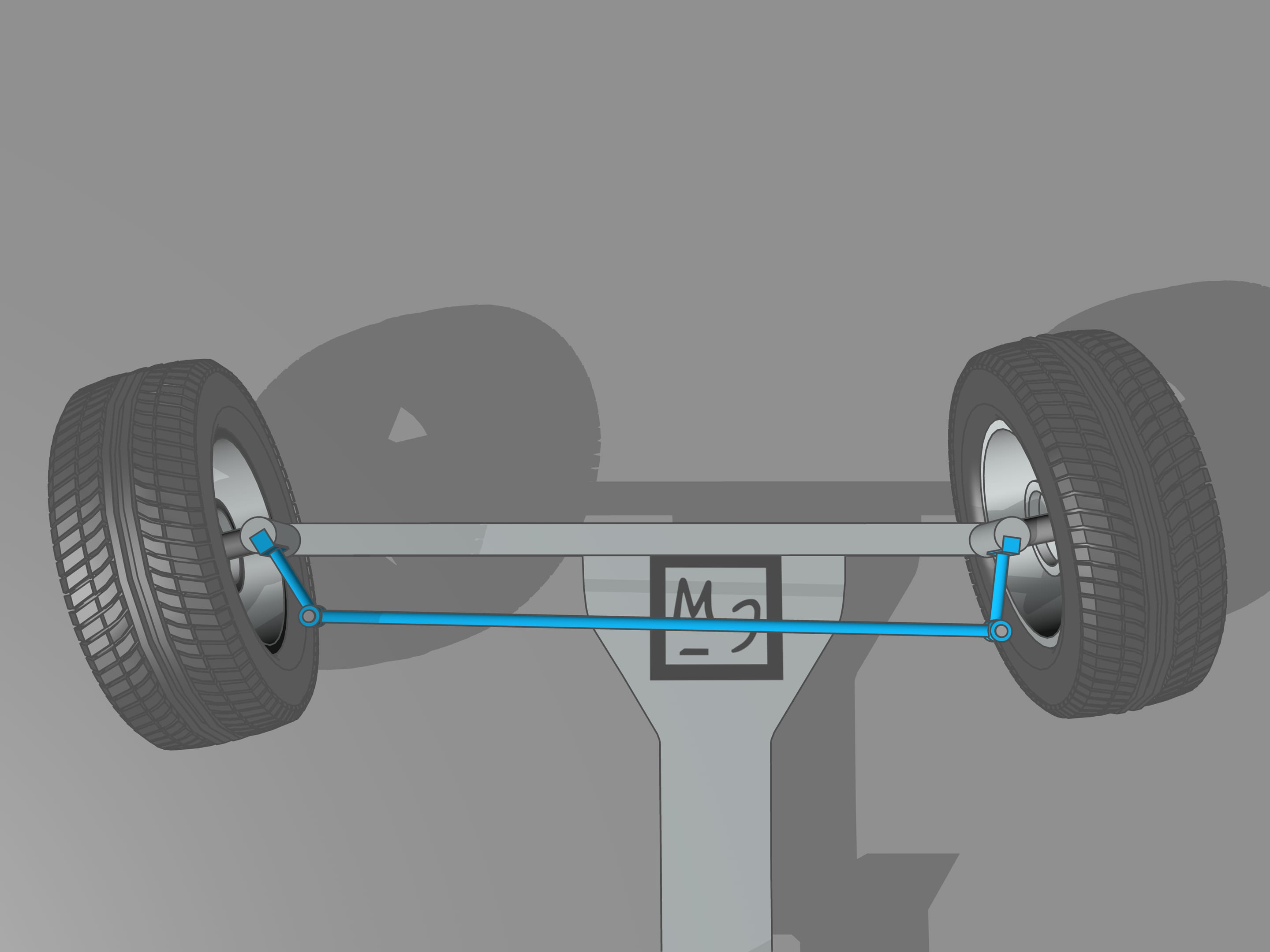
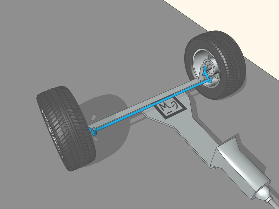
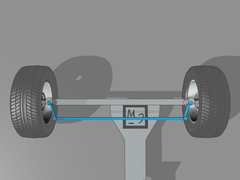
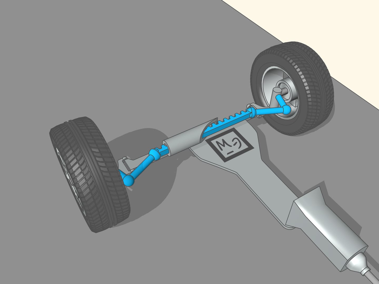
It happens that also here the geometry comes to our aid, and specifically with the isosceles trapezium, that we know from school: a quadrilateral with two parallel sides, called bases, and two other non-parallel sides equal to each other. If we choose the correct lengths of the sides of the trapezium, we obtain the conditions necessary for the optimal control: the prolongations of the axes of the front wheels intersect at a point lying on the prolongation of the axis of the rear wheels. And this point is the instantaneous centre of curvature.

This control system was invented by a French master craftsman, Charles Jeantland, which applied it to the front wheels of the carts. But for carts, moving at low speeds, this invention was not so essential as for cars, and was forgotten. Only after three quarters of a century, two German engineers, two fathers of the automobile, Gottlieb Daimler and Wilhelm Karl Friedrich Michael Benz, building their cars, returned to the Jeantland trapezium. Daimler in 1889 obtained a patent for his “method of independent control of front wheels with different radii of curvature.” And in1893 Benz obtained a patent for his “construction of a control system with control circles tangent to the wheels.” After solving the problem of control of the front steering wheels and other important technical issues, Karl Benz built his famous car “Viktoria”, with four independent wheels.
From the mathematical point of view, the trapezium does not allow to create the conditions necessary to ensure that the intersection point of the prolongations of the axes of the front wheels will always lie on the prolongation of the axis of the rear wheels. Using the trapezium, this point will lie a little bit far from the line of the rear axle. But why we have so long spoken of the trapezium, you ask? We worried too soon: we simply must not apply the mathematical rigor to technical problems without using the common sense. In order the prolongation of the axes of the front wheels will always intersect at a point on the prolongation of the axis of the rear wheels is necessary that the length of the smaller base of the trapezium change a little. For the usual length of its base, which is more than one meter long, the necessary changes would consist of the length of a centimetre, which is lower than the interstices between the joints and the tolerance in manufacturing.
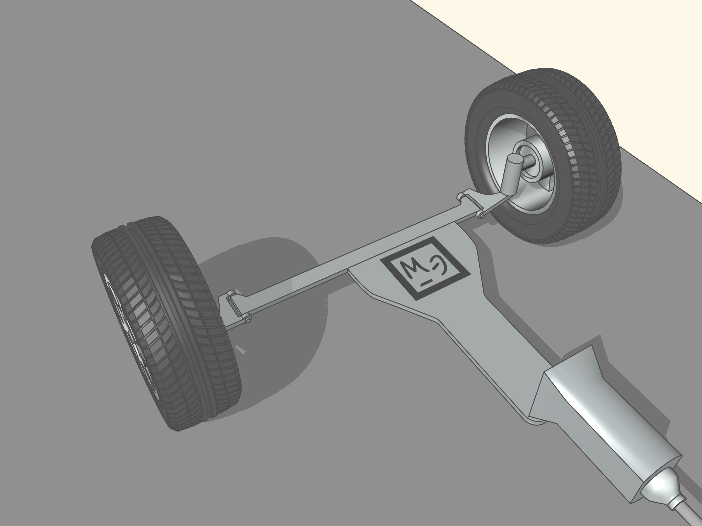
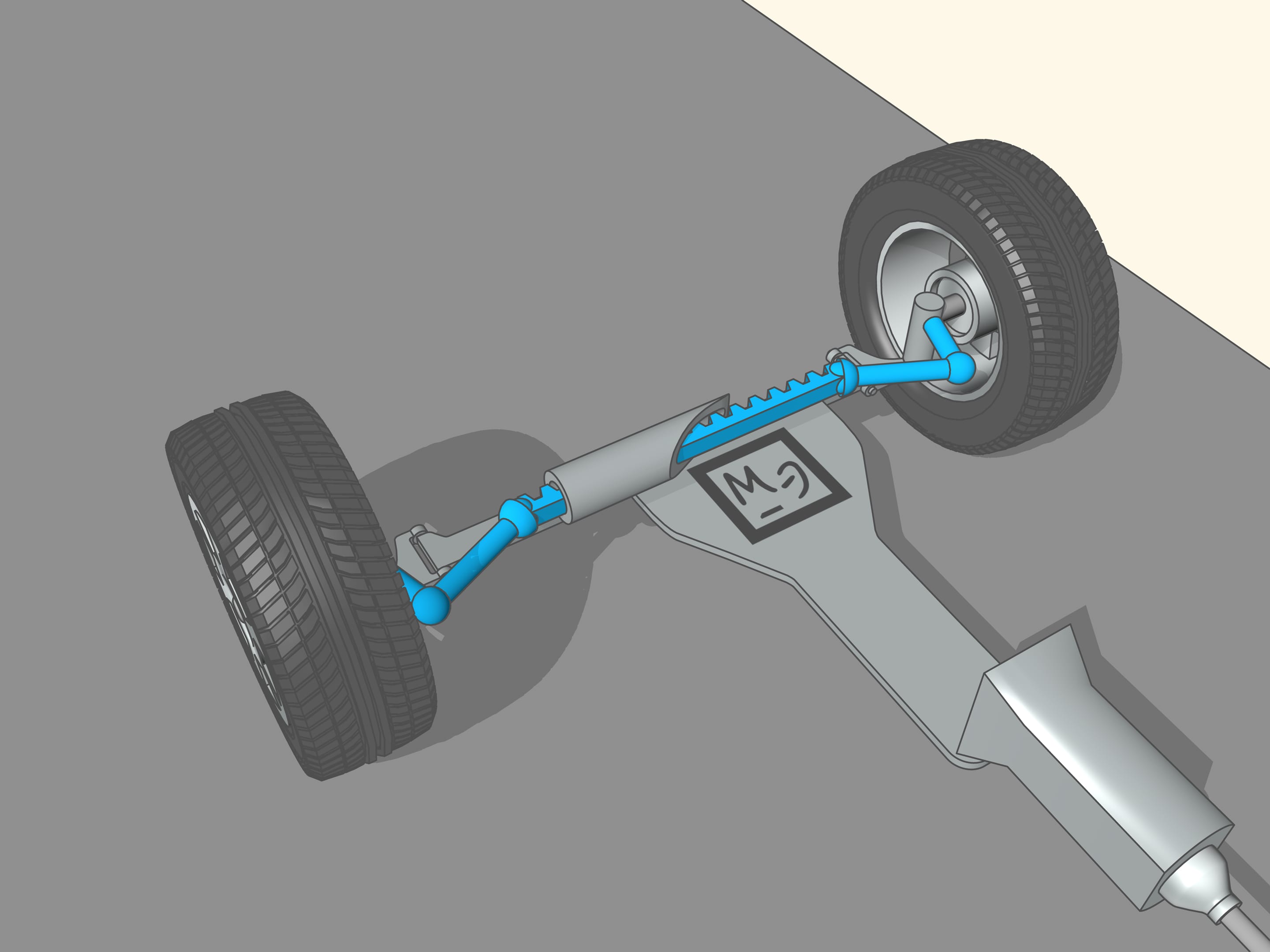
From the time of the creation of the first car the speed is increased dramatically. So also grew the need for a better control of the front wheels. In addition, the trapezium is a flat geometric figure: this method of control of the front wheels can be used only with non-independent front suspension, i.e., when the wheels are rigidly connected to each other and the straight line joining their centres is always parallel to the plane of the trapezium. Now this system can be found in the trucks. In modern cars the wheels suspensions are independent, the wheels can move in vertical direction with respect to one another. To control the steering of these wheels, more complex mechanisms are used, no longer planar, often with a central element with the shape of a rack. Even in this case it is a problem for mathematicians and engineers to calculate the different elements. But for historical reasons these mechanisms continue to be called steering trapezium.

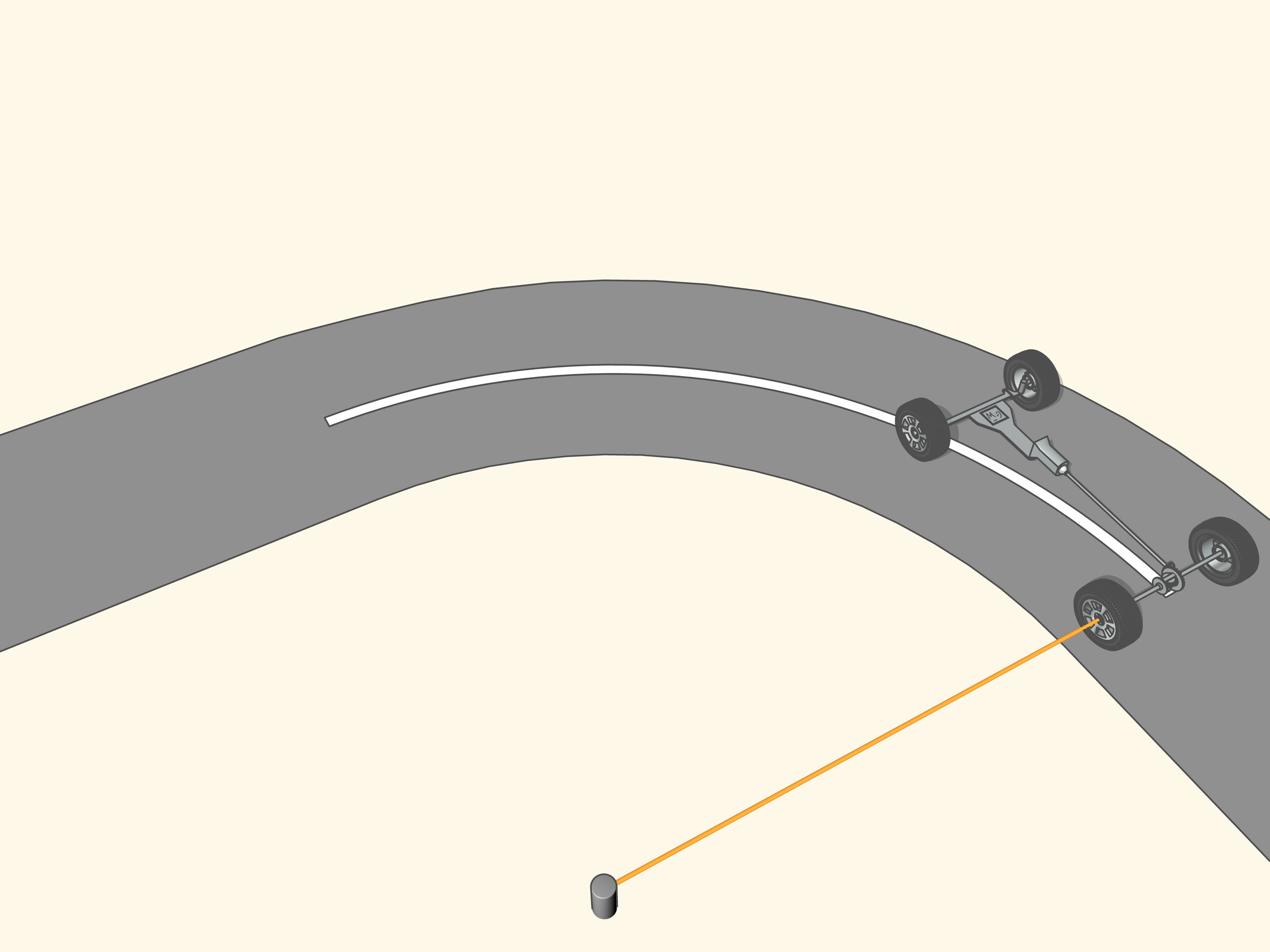
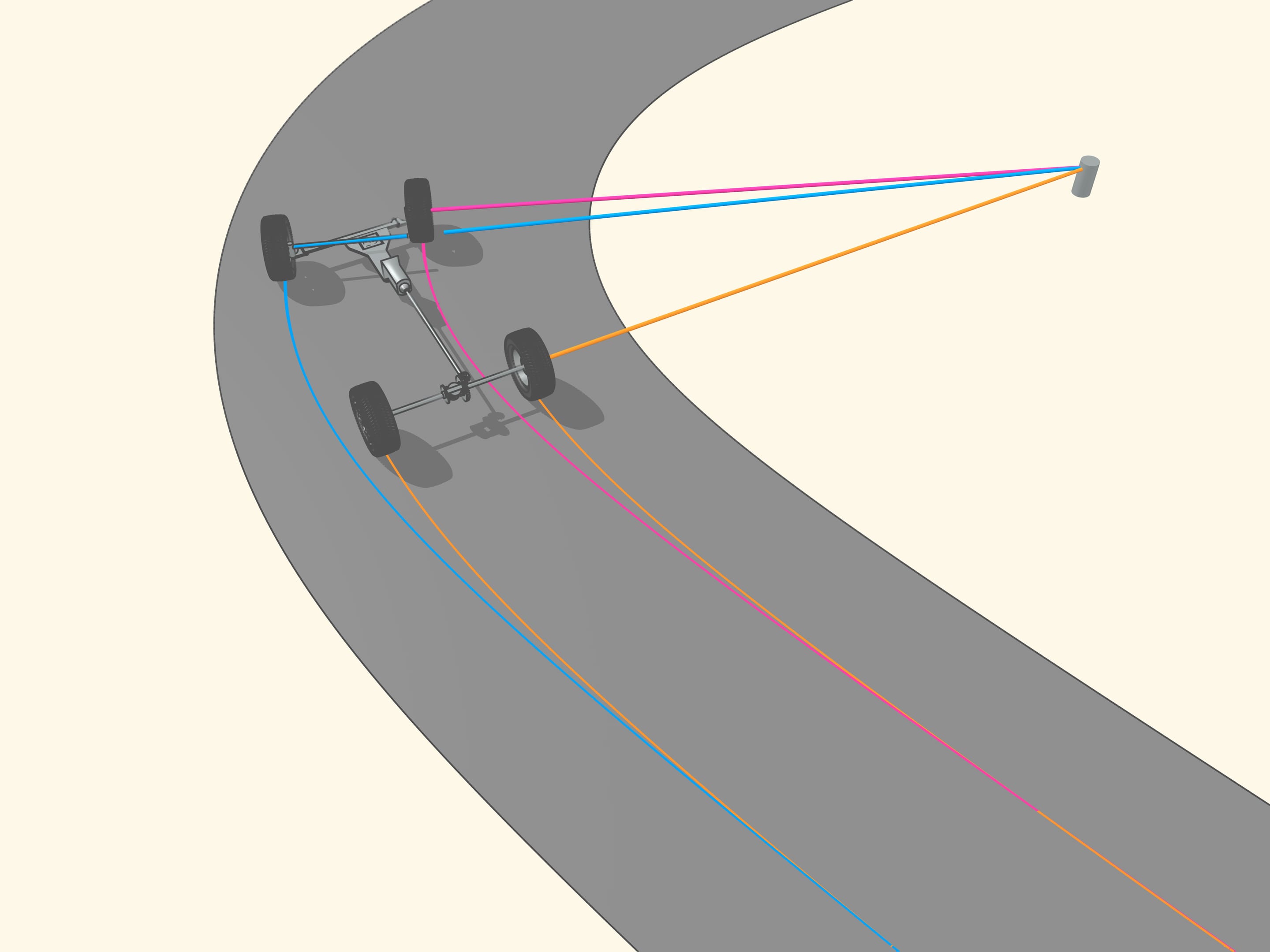
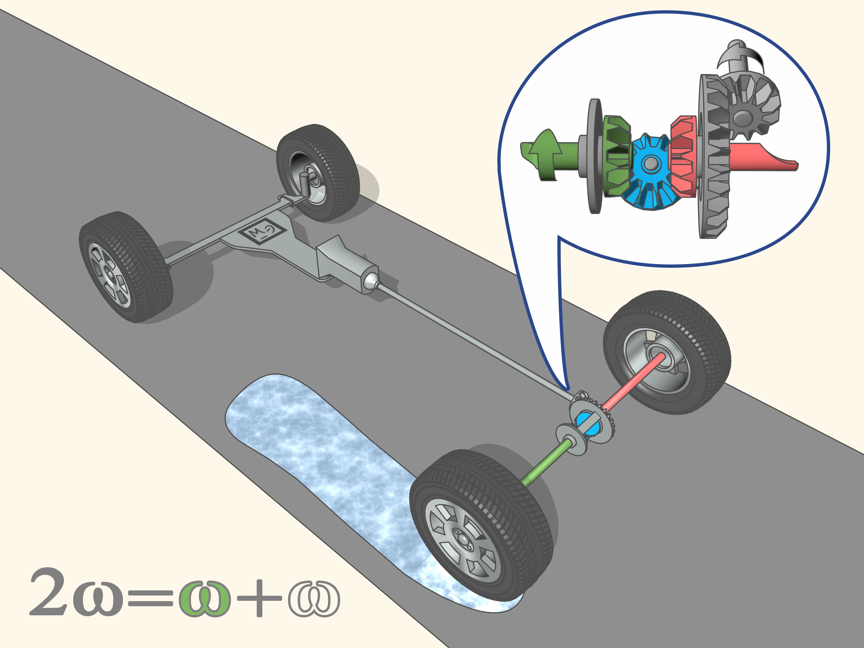
With the steering of the car another question is emerging, still related to the geometry. The length of a circle of radius R is equal, you will recall, to 2R, and the length of an arc of amplitude is equal to R. When the car moves along an arc of a circle, the outside front wheel, furthest from the centre of curvature, moves along an arc of radius greater than the inside. The same holds for the rear wheels: the outer wheel describes an arc of length greater than the inner wheel. And since the rays are different, so the lengths of the paths of the wheels connected by the same axle must be different. In the opposite case one of the two wheels should skid, and this should decrease the control of the car.
In the case when the axis of the wheels is not the primary, i.e., the wheels are not driving — in our case the front wheels- it is simple: each wheel turns with its speed needed to go through the desired curve without skidding.
But how to do so that the driving wheels — in our case the rear wheels — on the one hand constantly move the car forward and on the other rotate at different speeds?
This problem is solved by the differential, a typical ’planetary mechanism’. A mechanism is called ’planetary’ if it has satellite mechanisms revolving around axes which in turn rotate.
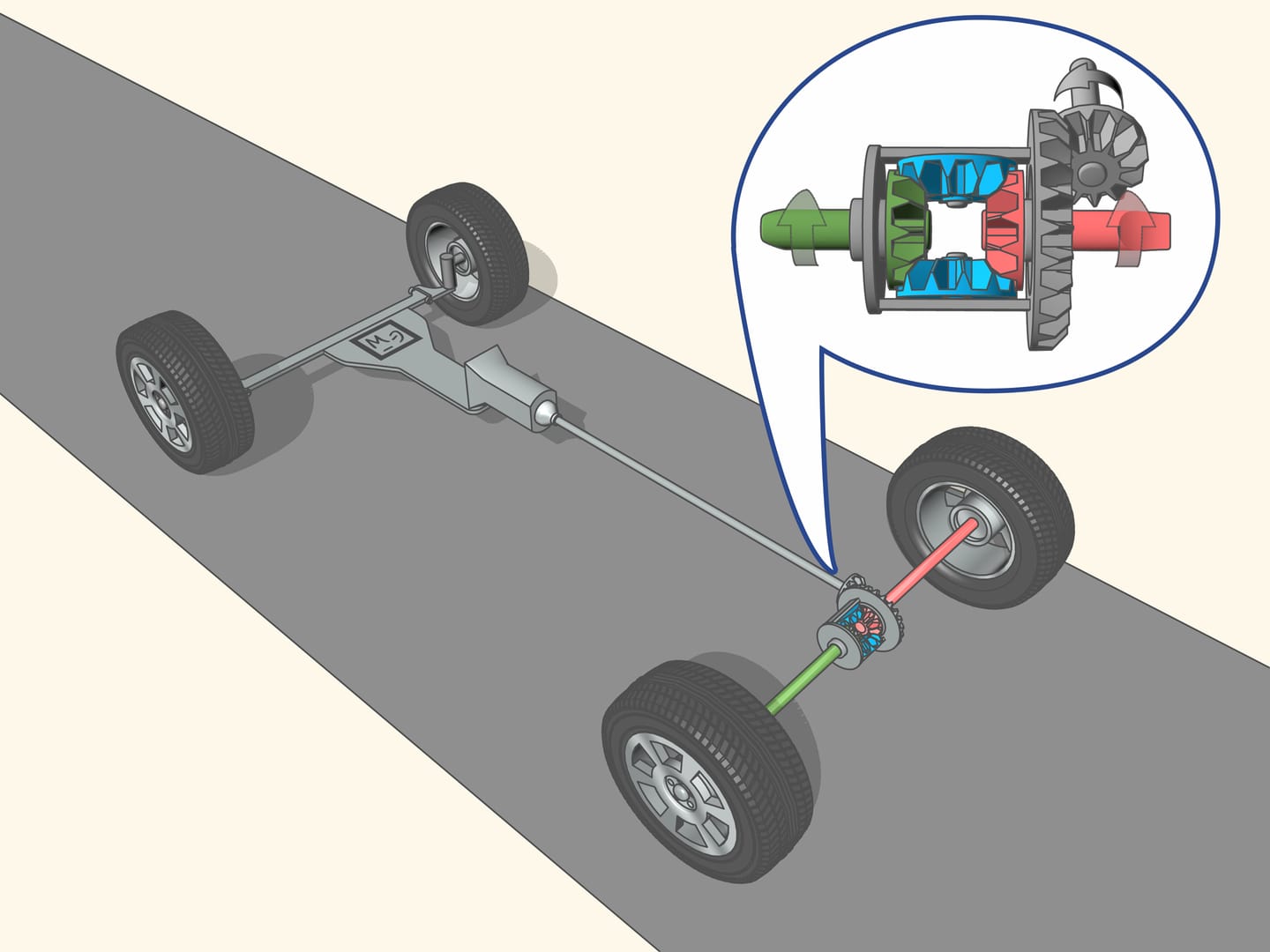
The drive shaft through the transmission, gives the rotation to the primary axle, namely, through the planetary mechanism, to the primary right and left shaft-axles. Whatever the speed at which the rear wheels spin, the speed of the mechanism will always be equal to the average speed of the drive shafts. Each wheel from the differential takes a lot of rotation, proportional to the length of its path, so that in total all the energy is converted into the forward movement of the car.
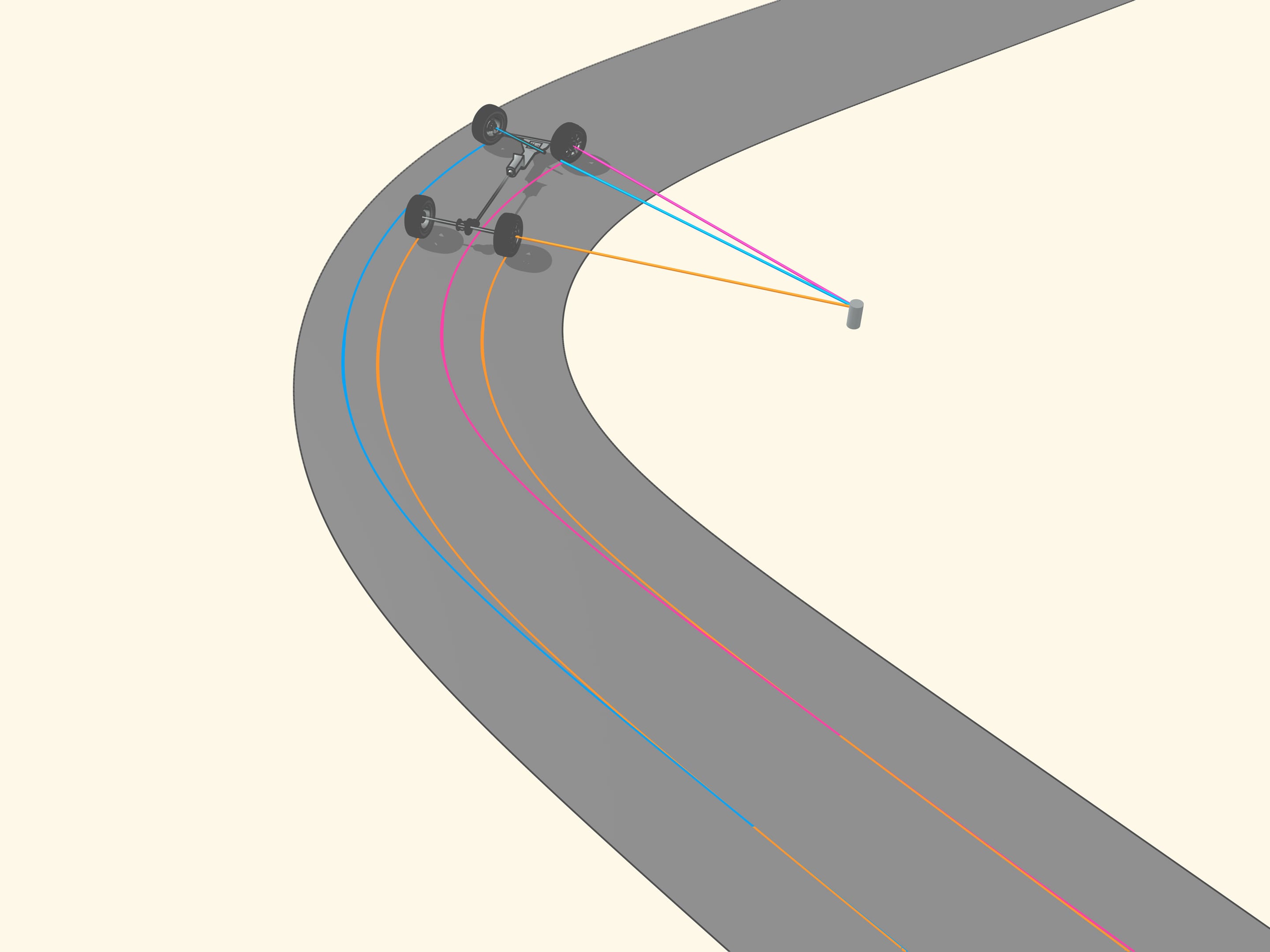
If the car moves on a straight road, and under the driving wheels there is the same soil type, i.e., with the same coefficient of friction, the wheels take from the mechanism the same amount of rotation, so that the drive shafts rotate (and the wheels together with them) at the same speed.
But if the friction coefficients are different, for example, while one side of the car passes over a patch of oil or over a layer of ice, then ...how the wheels will move if this happens? For the non driving wheels it is quite simple, since they are independent of each other, and do not push the car, so if one of them ends up on the ice, it stops spinning, and the control becomes very low.
But now also the driving wheel on the left rear ends up on the ice. For the right wheel on the asphalt, the control is high, while for the left wheel on the ice, it is almost absent. Consequently, the left wheel turns more easily, and it begins to take at its side all the rotation that the mechanism splits to the two shafts. Since the amount of speed, as we have said, is constant, if an axle shaft turns very quickly, the other will not rotate. To start moving in this situation, when one of the driving wheels has lost grip with the ground (for example, on the ice), while the other has not, it is impossible.
This would appear as a defect in the differential. The engineers, in fact, seek to improve the differential, while retaining its basic property, which is that of the optimal control in steering, and by reducing the unpleasant effects, such as not allowing one axle to spin when the difference of angular speed is high. But, it seems, up to now nothing has changed, as well as the laws of geometry are always the same.
Other etudes in “Mathematics and Technology”